Page 108 - Programmable Logic Controllers, Fifth Edition - Mobile version
P. 108

not directly control an output field device. The internal
                              A
                                      B
                                               C
                                                         Y
                                                                         output operates just like any output that is controlled by
                                                                         programmed logic; however, the output is used strictly
                                      D        E
                                                                         for internal purposes.
                                                                           The advantage of using internal outputs is that there
                              F
                                                                         are many situations in which an output instruction is re-
                                                                         quired in a program but no physical connection to a field
                        Boolean equation: Y = (ABC) + (ADE) + (FE) + (FDBC)    device is needed. If there are no physical outputs wired
                                                                         to a bit address, the address can be used as an internal
                   Figure 5-39  Original circuit.
                                                                         storage point. Internal storage bits or points can be pro-
                            A      B       C               Y             grammed by the user to perform relay functions without
                                                                         occupying a physical output. In this way internal outputs
                            A      D       E                             can minimize output module point requirements when-
                                                                         ever practical.
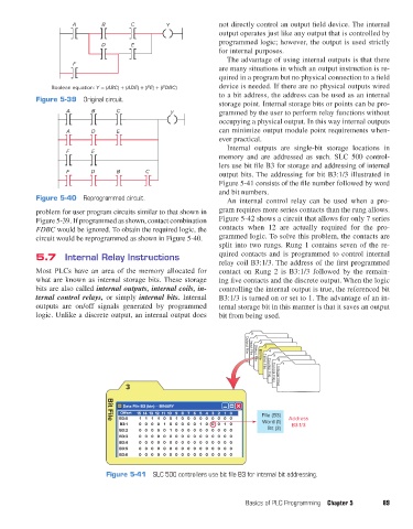
                                                                           Internal outputs are single-bit storage locations in
                            F      E
                                                                         memory and are addressed as such. SLC 500 control-
                                                                         lers use bit file B3 for storage and addressing of internal
                            F      D       B       C
                                                                         output bits. The addressing for bit B3:1/3 illustrated in
                                                                         Figure 5-41 consists of the file number followed by word
                                                                         and bit numbers.
                   Figure 5-40  Reprogrammed circuit.                      An internal control relay can be used when a pro-

                   problem for user program circuits similar to that shown in   gram requires more series contacts than the rung allows.
                   Figure 5-39. If programmed as shown, contact combination   Figure 5-42 shows a circuit that allows for only 7 series
                   FDBC would be ignored. To obtain the required logic, the   contacts when 12 are actually required for the pro-
                   circuit would be reprogrammed as shown in Figure 5-40.  grammed logic. To solve this problem, the contacts are
                                                                         split into two rungs. Rung 1 contains seven of the re-
                   5.7  Internal Relay Instructions                      quired contacts and is programmed to control internal
                                                                         relay coil B3:1/3. The address of the first programmed
                   Most  PLCs  have  an  area  of  the  memory allocated for   contact on Rung 2 is B3:1/3 followed by the remain-
                   what are known as internal storage bits. These storage   ing five contacts and the discrete output. When the logic
                   bits are also called internal outputs, internal coils, in-  controlling the internal output is true, the referenced bit
                   ternal control relays, or simply internal bits. Internal   B3:1/3 is turned on or set to 1. The advantage of an in-
                   outputs are on/off signals generated by programmed    ternal storage bit in this manner is that it saves an output
                   logic. Unlike a discrete output, an internal output does   bit from being used.

                                                                                  0
                                                                                    1
                                                                                     2
                                                                                      3
                                                                                        4
                                                                                         5
                                                                                 Output File
                                                                                  Input File
                                                                                          6
                                                                                     Bit File
                                                                                    Status File
                                                                                            7
                                                                                      Timer File
                                                                                        Counter File
                                                                                         Control Files
                                              3                                           Integer Files
                                             Data File B3 (bin) -- BINARY
                                            O set  15 14 13 12 11 10 98 76 5432 10    File (B3)
                                            B3:0  1  1  1  10 01 000000000                    Address
                                        Bit File
                                            B3:1  0 000 10 0 000 10 00 10             Word (1)  B3:1/3
                                            B3:2  0 000 01 0 000000000                 Bit (3)
                                            B3:3  0 00000 0 000000000
                                            B3:4  0 00000 0 000000000
                                            B3:5  0 00000 0 000000000
                                            B3:6  0 00000 0 000000000
                                        Figure 5-41  SLC 500 controllers use bit file B3 for internal bit addressing.


                                                                                 Basics of PLC Programming  Chapter 5    89


          pet73842_ch05_074-097.indd   89                                                                               05/11/15   4:17 PM
   103   104   105   106   107   108   109   110   111   112   113