
Page 104 - Programmable Logic Controllers, Fifth Edition - Mobile version
P. 104
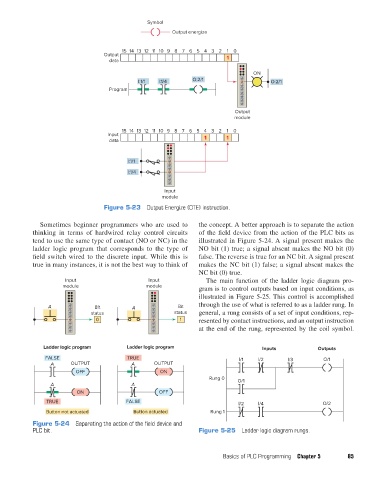
Symbol
                                                                Output energize

                                                15 14 13 12 11 10 98 76 54 32     1  0
                                          Output                                  1
                                            data

                                                                                           ON
                                                     I:1/1  I:1/4      O:2/1                    O:2/1
                                            Program


                                                                                     Output
                                                                                     module
                                                15 14 13 12 11 10 98 76 54 32     1  0
                                           Input                           1      1
                                            data


                                                  I:1/1
                                                  I:1/4


                                                              Input
                                                             module
                                          Figure 5-23  Output Energize (OTE) instruction.

                     Sometimes beginner programmers who are used to      the concept. A better approach is to separate the action
                   thinking  in  terms  of  hardwired  relay  control  circuits   of the field device from the action of the PLC bits as
                   tend to use the same type of contact (NO or NC) in the   illustrated in Figure 5-24. A signal present makes the
                   ladder logic program that corresponds to the type of   NO bit (1) true; a signal absent makes the NO bit (0)
                   field switch wired to the discrete input. While  this  is   false. The reverse is true for an NC bit. A signal present
                   true in many instances, it is not the best way to think of   makes the NC bit (1) false; a signal absent makes the
                                                                         NC bit (0) true.
                              Input                      Input             The main function of the ladder logic diagram pro-
                             module                     module           gram is to control outputs based on input conditions, as
                                                                         illustrated in Figure 5-25. This control is accomplished
                        A              Bit         A              Bit    through the use of what is referred to as a ladder rung. In
                                      status                     status  general, a rung consists of a set of input conditions, rep-
                                        0                          1     resented by contact instructions, and an output instruction
                                                                         at the end of the rung, represented by the coil symbol.


                       Ladder logic program       Ladder logic program                        Inputs            Outputs

                       FALSE                      TRUE                                I/1   I/2       I/3         O/1
                         A     OUTPUT              A      OUTPUT
                                 OFF                        ON
                                                                            Rung 0    O/1
                         A                         A
                                 ON                         OFF
                       TRUE                      FALSE                                I/2   I/4                  O/2
                       Button not actuated          Button actuated          Rung 1

                   Figure 5-24  Separating the action of the field device and
                   PLC bit.                                              Figure 5-25  Ladder logic diagram rungs.


                                                                                 Basics of PLC Programming  Chapter 5    85


          pet73842_ch05_074-097.indd   85                                                                               05/11/15   4:17 PM