
Page 100 - Programmable Logic Controllers, Fifth Edition - Mobile version
P. 100
established to standardize the multiple languages associ-
Horizontal scanning order
ated with PLC programming by defining the following
five standard languages:
Vertical • Ladder Diagram (LD)—a symbolic depiction of
scanning instructions arranged in rungs similar to ladder-
order Return
for next formatted schematic diagrams.
scan • Function Block Diagram (FBD)—a graphical de-
piction of process flow using simple and complex
interconnecting blocks.
End of ladder • Sequential Function Chart (SFC)—a graphical
depiction of interconnecting steps, actions, and
Figure 5-13 Scanning can be vertical or horizontal. transitions.
• Instruction List (IL)—a low-level, text-based
(F igure 5-13). Allen-Bradley PLCs use the horizontal language that uses mnemonic instructions.
scan by rung method. In this system, the processor exam- • Structured Text (ST)—a high-level, text-based lan-
ines input and output instructions from the first com- guage such as BASIC, C, or PASCAL specifically
mand, top left in the program, horizontally, rung by rung. developed for industrial control applications.
Modicon PLCs use the vertical scan by column method.
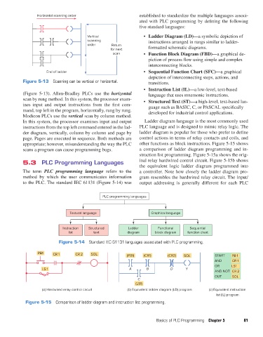
In this system, the processor examines input and output Ladder diagram language is the most commonly used
instructions from the top left command entered in the lad- PLC language and is designed to mimic relay logic. The
der diagram, vertically, column by column and page by ladder diagram is popular for those who prefer to define
page. Pages are executed in sequence. Both methods are control actions in terms of relay contacts and coils, and
appropriate; however, misunderstanding the way the PLC other functions as block instructions. Figure 5-15 shows
scans a program can cause programming bugs. a comparison of ladder diagram programming and in-
struction list programming. Figure 5-15a shows the orig-
5.3 PLC Programming Languages inal relay hardwired control circuit. Figure 5-15b shows
the equivalent logic ladder diagram programmed into
The term PLC programming language refers to the a controller. Note how closely the ladder diagram pro-
method by which the user communicates information gram resembles the hardwired relay circuit. The input/
to the PLC. The standard IEC 61131 (Figure 5-14) was output addressing is generally different for each PLC
PLC programming languages
Textural language Graphical language
Instruction Structured Ladder Functional Sequential
list text diagram block diagram function chart
Figure 5-14 Standard IEC 61131 languages associated with PLC programming.
PB1 CR 1 CR 2 SOL (PB1) (CR1) (CR2) SOL START PB 1
AND CR 1
OR LS1
LS 1 A B D Y
AND NOT CR 2
OUT SOL
C
(LS1)
(a) Hardwired relay control circuit (b) Equivalent ladder diagram (LD) program (c) Equivalent instruction
list (IL) program
Figure 5-15 Comparison of ladder diagram and instruction list programming.
Basics of PLC Programming Chapter 5 81
pet73842_ch05_074-097.indd 81 05/11/15 4:17 PM