Page 105 - Programmable Logic Controllers, Fifth Edition - Mobile version
P. 105

in at least one path, the rung condition and Output Ener-
                    Rung 0   F       T       T          F            having logical continuity. When logical continuity exists
                                                                     gize instruction are said to be true. The rung condition and
                                                                     OTE instruction are false if no logical continuity path has
                    Rung 1   T                          T
                                                                     been established. During controller operation, the proces-
                                                                     sor evaluates the rung logic and changes the state of the
                    Rung 2   F       T       T          T            outputs according to the logical continuity of rungs.

                                                        T
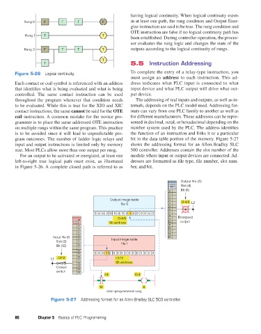
                             T                                       5.5  Instruction Addressing

               Figure 5-26   Logical continuity.                     To complete the entry of a relay-type instruction, you
                                                                     must assign an  address to each instruction. This ad-
               Each contact or coil symbol is referenced with an address   dress indicates what PLC input is connected to what
               that identifies what is being evaluated and what is being   input device and what PLC output will drive what out-
               controlled.  The same contact instruction can be used   put device.
               throughout the program whenever that condition needs     The addressing of real inputs and outputs, as well as in-
               to be evaluated. While this is true for the XIO and XIC   ternals, depends on the PLC model used. Addressing for-
               contact instructions, the same cannot be said for the OTE   mats can vary from one PLC family to another as well as
               coil instruction. A common mistake for the novice pro-  for different manufacturers. These addresses can be repre-
               grammer is to place the same addressed OTE instruction   sented in decimal, octal, or hexadecimal depending on the
               on multiple rungs within the same program. This practice   number system used by the PLC. The address identifies
               is to be avoided since it will lead to unpredictable pro-  the function of an instruction and links it to a particular
               gram outcomes. The number of ladder logic relays and   bit in the data table portion of the memory. Figure 5-27
               input and output instructions is limited only by memory   shows the addressing format for an Allen-Bradley SLC
               size. Most PLCs allow more than one output per rung.  500 controller. Addresses contain the slot number of the
                  For an output to be activated or energized, at least one   module where input or output devices are connected. Ad-
               left-to-right  true  logical  path  must  exist,  as  illustrated   dresses are formatted as file type, file number, slot num-
               in Figure 5-26. A complete closed path is referred to as   ber, and bit.


                                                                                             Output file (O)
                                                                                             Slot (4)
                                                                                       0     Bit (6)
                                                                                       1
                                                                                       2
                                                            Output image table         3
                                                                 file 0                 4     O:4/6 L2
                                                                                       5
                                                                                       6
                                                    0  0  0  0  0  0  0  0  0  1  0  0  0  0  0  0  7
                                                                                       8
                                                               O:4/6                   9    Energized
                                                           Bit address                 10    output
                                             0                                         11
                                             1                                         12
                                             2                                         13
                                             3                                         14
                                 Input file (I)  4           Input image table          15
                                   Slot (3)  5                   file 1
                                   Bit (12)  6
                                             7
                                             8
                                             9      0  0  0  1  0  0  0  0  0  0  0  0  0  0  0  0
                                L1  I:3/12   10               I:3/12
                                             11
                                             12               Bit address
                                   Closed    13
                                             14
                                   switch    15
                                                         I:3           O:4
                                                       12                  6
                                                          User-programmed rung
                                Figure 5-27  Addressing format for an Allen-Bradley SLC 500 controller.


               86         Chapter 5  Basics of PLC Programming


          pet73842_ch05_074-097.indd   86                                                                               05/11/15   4:17 PM
   100   101   102   103   104   105   106   107   108   109   110