
Page 279 - Programmable Logic Controllers, Fifth Edition - Mobile version
P. 279
L1 Input Ladder logic program Output L2
Stop_Start_ Timer 2:O.Data.1
Stop_Start_ Timer <Local:1:I.Data.0 Step_Timer.DN TON
Timer On Delay EN 2:O.Data.2
Timer Step_Timer
Preset 5000 DN 2:O.Data.3
Accum 0 2:O.Data.4
2:O.Data.5
2:O.Data.6
2:O.Data.7
Step_Timer.DN SQO
Sequencer Output EN
Array SQO_Data_Array[0]
Mask 16#0000_00FE DN
Dest Output _Card
<Local:2:0.Data>
Control Control_Tag
Length 5
Position 0
Output states entered into sequencer data array
[–] SQO_Data_Array {. . .}
[+] SQO_Data_Array[0] 2#0000_0000_0000_0000_0000_0000_0000_0000
[+] SQO_Data_Array[1] 2#0000_0000_0000_0000_0000_0000_0000_0010
[+] SQO_Data_Array[2] 2#0000_0000_0000_0000_0000_0000_0000_01 10
[+] SQO_Data_Array[3] 2#0000_0000_0000_0000_0000_0000_0001_0000
[+] SQO_Data_Array[4] 2#0000_0000_0000_0000_0000_0000_1 1 00_0000
[+] SQO_Data_Array[5] 2#0000_0000_0000_0000_0000_0000_1 11 1_ 0000
Outputs which are On for each step
Outputs Step
7 6 5 4 3 2 1 0
0
On 1
On On 2
On 3
On On On 4
On On On On 5
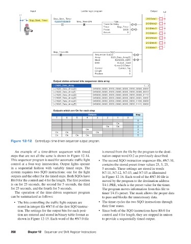
Figure 12-12 ControlLogix time-driven sequencer output program.
An example of a time-driven sequencer with timed is moved from the file by the program to the desti-
steps that are not all the same is shown in Figure 12-14. nation output word O:2 as previously described.
This sequencer program is used for automatic traffic light • The second SQO instruction sequencer file, #N7:10,
control at a four-way intersection. Output lights operate contains the stored preset timer values 25, 5, 25,
in a sequential fashion with variably timed steps. The 5 seconds. These settings are stored in words
system requires two SQO instructions: one for the light N7:11, N7:12, N7:13, and N7:15 as illustrated
outputs and the other for the timed steps. Both SQOs have in Figure 12-16. Each word of the #N7:10 file is
R6:0 for the control and 4 for the length. The first position moved by the program to the destination address
is on for 25 seconds, the second for 5 seconds, the third T4:1.PRE, which is the preset value for the timer.
for 25 seconds, and the fourth for 5 seconds. The program moves information from this file to
The operation of the time-driven sequencer program timer T4:1’s preset. The mask allows the proper data
can be summarized as follows: to pass and blocks the unnecessary data.
• The bits controlling the traffic light outputs are • The timer cycles the two SQO instructions through
stored in integer file #N7:0 of the first SQO instruc- their four states.
tion. The settings for the output bits for each posi- • Since both of the SQO instructions have R6:0 for
tion are entered and stored in binary table format as control and 4 for length, they are stepped in unison
shown in Figure 12-15. Each word of the #N7:0 file to provide a sequentially timed output.
260 Chapter 12 Sequencer and Shift Register Instructions
pet73842_ch12_252-280.indd 260 03/11/15 7:19 PM