
Page 354 - Programmable Logic Controllers, Fifth Edition - Mobile version
P. 354
Ladder logic program
LogixDesigner
RSLogix
RSLinx
RSWho
File View Communications
ControlLogix
RSWho RSLinx
Controller
Configure Drivers...
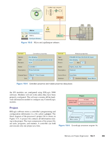
Figure 15-3 RSLinx and LogixDesigner software.
General Controllers properties General Modules properties
Vendor: Allen-Bradley Type: 1756-IB16 16 Point 10V-31.2V DC Input
Type: 1756-L55 ControlLogix5555Controller Vendor: Allen-Bradley
Revision: 10.24 Parent: Local Slot: 0
Name: Controller 1 Name: Digital_Input_16pt
Description: Prime Controller Description: Optional
Chassis Type: 1756-A7 7-Slot Chassis Comm Form: Input Data
Slot: 1 Revision: 1 Electronic Keying Exact Match
Figure 15-4 Controllers properties and modules properties dialog boxes.
the I/O modules are configured using RSLogix 5000
software. Modules will not work unless they have been
properly configured. The software contains all the hard- Project
ware information needed to configure any ControlLogix I/O data
module. Controller tags
(global data)
System-shared data
Project Task
RSLogix software stores a controller’s programming and Program
configuration information in a file called a project. The
block diagram of the processor’s project file is shown in Other routines Program tags
Figure 15-5. A project file contains all information relat- Main routine (local data)
ing to the project. The main components of the project file
are tasks, programs, and routines. A controller can hold
and execute only one project at a time. Figure 15-5 ControlLogix processor program file.
Memory and Project Organization Part 1 335
pet73842_ch15_333-394.indd 335 03/11/15 7:32 PM