
Page 353 - Programmable Logic Controllers, Fifth Edition - Mobile version
P. 353
Part 1 Memory and
Project Organization
Memory Layout Part Objectives
ControlLogix processors provide a flexible memory
structure. There are no fixed areas of memory allocated After completing this part, you will be able to:
for specific types of data or for I/O. The internal memory • Outline project organization
organization of a ControlLogix controller is configured • Define tasks, programs, and routines
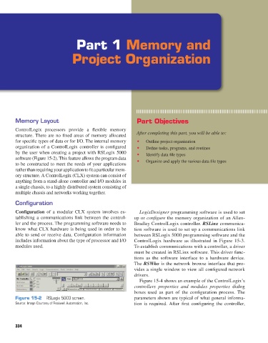
by the user when creating a project with RSLogix 5000 • Identify data file types
software (Figure 15-2). This feature allows the program data
to be constructed to meet the needs of your applications • Organize and apply the various data file types
rather than requiring your application to fit a particular mem-
ory structure. A ControlLogix (CLX) system can consist of
anything from a stand-alone controller and I/O modules in
a single chassis, to a highly distributed system consisting of
multiple chassis and networks working together.
Configuration
Configuration of a modular CLX system involves es- LogixDesigner programming software is used to set
tablishing a communications link between the control- up or configure the memory organization of an Allen-
ler and the process. The programming software needs to Bradley ControlLogix controller. RSLinx communica-
know what CLX hardware is being used in order to be tion software is used to set up a communications link
able to send or receive data. Configuration information between RSLogix 5000 programming software and the
includes information about the type of processor and I/O ControlLogix hardware as illustrated in Figure 15-3.
modules used. To establish communications with a controller, a driver
must be created in RSLinx software. This driver func-
tions as the software interface to a hardware device.
The RSWho is the network browse interface that pro-
vides a single window to view all configured network
drivers.
Figure 15-4 shows an example of the ControlLogix’s
controllers properties and modules properties dialog
boxes used as part of the configuration process. The
Figure 15-2 RSLogix 5000 screen. parameters shown are typical of what general informa-
Source: Image Courtesy of Rockwell Automation, Inc. tion is required. After first configuring the controller,
334
pet73842_ch15_333-394.indd 334 03/11/15 7:32 PM