
Page 37 - Programmable Logic Controllers, Fifth Edition - Mobile version
P. 37
2.1 The I/O Section
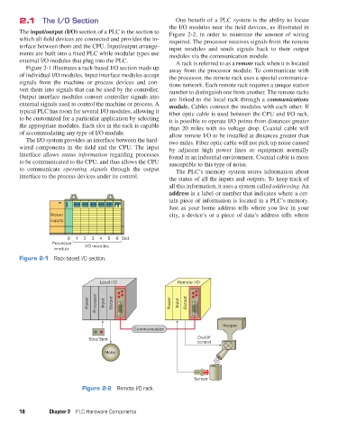
One benefit of a PLC system is the ability to locate
the I/O modules near the field devices, as illustrated in
The input/output (I/O) section of a PLC is the section to Figure 2-2, in order to minimize the amount of wiring
which all field devices are connected and provides the in- required. The processor receives signals from the remote
terface between them and the CPU. Input/output arrange- input modules and sends signals back to their output
ments are built into a fixed PLC while modular types use modules via the communication module.
external I/O modules that plug into the PLC. A rack is referred to as a remote rack when it is located
Figure 2-1 illustrates a rack-based I/O section made up away from the processor module. To communicate with
of individual I/O modules. Input interface modules accept the processor, the remote rack uses a special communica-
signals from the machine or process devices and con- tions network. Each remote rack requires a unique station
vert them into signals that can be used by the controller. number to distinguish one from another. The remote racks
Output interface modules convert controller signals into are linked to the local rack through a communications
external signals used to control the machine or process. A module. Cables connect the modules with each other. If
typical PLC has room for several I/O modules, allowing it fiber optic cable is used between the CPU and I/O rack,
to be customized for a particular application by selecting it is possible to operate I/O points from distances greater
the appropriate modules. Each slot in the rack is capable than 20 miles with no voltage drop. Coaxial cable will
of accommodating any type of I/O module. allow remote I/O to be installed at distances greater than
The I/O system provides an interface between the hard- two miles. Fiber optic cable will not pick up noise caused
wired components in the field and the CPU. The input by adjacent high power lines or equipment normally
interface allows status information regarding processes found in an industrial environment. Coaxial cable is more
to be communicated to the CPU, and thus allows the CPU susceptible to this type of noise.
to communicate operating signals through the output The PLC’s memory system stores information about
interface to the process devices under its control. the status of all the inputs and outputs. To keep track of
all this information, it uses a system called addressing. An
address is a label or number that indicates where a cer-
tain piece of information is located in a PLC’s memory.
Just as your home address tells where you live in your
Power city, a device’s or a piece of data’s address tells where
supply
0 1 2 3 4 5 6 Slot
Processor I/O modules
module
Figure 2-1 Rack-based I/O section.
Local I/O Remote I/O
Power Processor Input Output Power Input Output
Hopper
Communication
Stop/Start On/O
control
Motor
Sensor
Figure 2-2 Remote I/O rack.
18 Chapter 2 PLC Hardware Components
pet73842_ch02_017-045.indd 18 03/11/15 3:43 PM