
Page 38 - Programmable Logic Controllers, Fifth Edition - Mobile version
P. 38
information about it resides in the PLC’s memory. That
way, if a PLC wants to find out information about a field
device, it knows to look in its corresponding address O:4/15 Output module in slot 4, terminal 15
location. Examples of addressing schemes include rack/ I:3/8 Input module in slot 3, terminal 8
slot-based, versions of which are used in Allen-Bradley O:6.0 Output module, slot 6
SLC 500 controllers, tag-based used in Allen-Bradley I:5.0 Input module, slot 5
ControlLogix controllers, and PC-based control used in
soft PLCs.
In general, rack/slot-based addressing elements include: Every input and output device connected to a discrete I/O
Type—The type determines if an input or output is module is addressed to a specific bit in the PLC’s memory.
being addressed. A bit is a binary digit that can be either 1 or 0. Analog I/O
Slot—The slot number is the physical location of the modules use a word addressing format, which allows the
I/O module. This may be a combination of the rack entire words to be addressed. The bit part of the address is
number and the slot number when using expansion usually not used; however, bits of the digital representation
racks. of the analog value can be addressed by the programmer
Word and Slot—The word and slot are used to iden- if necessary. Figure 2-4 illustrates bit level and word level
tify the actual terminal connection in a particular I/O addressing as it applies to an SLC 500 controller.
module. A discrete module usually uses only one Tag-based memory structures are the newest type of PLC
word, and each connection corresponds to a different memory addressing. Figure 2-5 illustrates the Allen-Brad-
bit that makes up the word. ley ControlLogix and CompactLogix tag-based addressing
format. Memory locations are defined by using base and
With a rack/slot address system the location of a alias tags. A base tag defines a memory location where data
module within a rack and the terminal number of a mod- are stored. An alias tag is used to create an alternate name
ule to which an input or output device is connected will (alias) for a tag. The alias tag is often used to create a tag
determine the device’s address. name to represent a real world input or output.
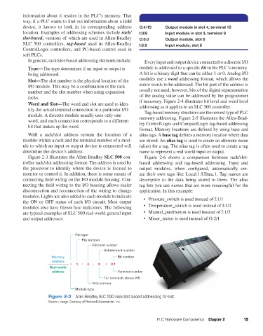
Figure 2-3 illustrates the Allen-Bradley SLC 500 con- Figure 2-6 shows a comparison between rack/slot-
troller rack/slot addressing format. The address is used by based addressing and tag-based addressing. Input and
the processor to identify where the device is located to output modules, when configured, automatically cre-
monitor or control it. In addition, there is some means of ate their own tags like Local:1:I.Data.1. Tag names are
connecting field wiring on the I/O module housing. Con- descriptive to the data being stored in them. The alias
necting the field wiring to the I/O housing allows easier tag lets you use names that are more meaningful for the
disconnection and reconnection of the wiring to change application. In this example:
modules. Lights are also added to each module to indicate
the ON or OFF status of each I/O circuit. Most output • Pressure_switch is used instead of I:1/1
modules also have blown fuse indicators. The following • Temperature_switch is used instead of I:1/2
are typical examples of SLC 500 real-world general input • Manual_pushbutton is used instead of I:1/3
and output addresses: • Mixer_motor is used instead of O:2/1
File type
File number
Element number
Subelement number
Memory Bit number
address
I 1 : 3 . 0 / 0 1
Real-world
address Terminal number
For terminals above #15
Slot number
Module type
Figure 2-3 Allen-Bradley SLC 500 rack/slot-based addressing format.
Source: Image Courtesy of Rockwell Automation, Inc.
PLC Hardware Components Chapter 2 19
pet73842_ch02_017-045.indd 19 03/11/15 3:43 PM