
Page 44 - Programmable Logic Controllers, Fifth Edition - Mobile version
P. 44
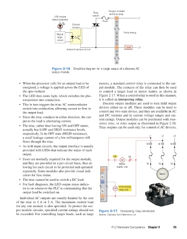
Triac     Output module
                                                                                terminal strip
                                            LED output               switch                       L1
                                          status indicator
                                                                           Fuse
                                                       Optical
                                                       isolator
                                                                                         Field wiring
                                             Digital
                                              logic
                                             circuit

                                                                                          Load    L2
                                                    Internal module circuit


                                          Figure 2-16  Simplified diagram for a single output of a discrete AC
                                          output module.


                     •  When the processor calls for an output load to be   motors, a standard control relay is connected to the out-
                       energized, a voltage is applied across the LED of   put module. The contacts of the relay can then be used
                       the opto-isolator.                                to control a larger load or motor starter, as shown in
                     •  The LED then emits light, which switches the pho-  Figure 2-17. When a control relay is used in this manner,
                       totransistor into conduction.                     it is called an interposing relay.
                     •  This in turn triggers the triac AC semiconductor   Discrete output modules are used to turn field output
                       switch into conduction, allowing current to flow to   devices either on or off. These modules can be used to
                       the output load.                                  control any two-state device, and they are available in AC
                     •  Since the triac conducts in either direction, the out-  and DC versions and in various voltage ranges and cur-
                       put to the load is alternating current.           rent ratings. Output modules can be purchased with tran-
                                                                         sistor, triac, or relay output as illustrated in Figure 2-18.
                     •  The triac, rather than having ON and OFF status,   Triac outputs can be used only for control of AC devices,
                       actually has LOW and HIGH resistance levels,
                       respectively. In its OFF state (HIGH resistance),
                       a small leakage current of a few milliamperes still                                L1     L2      L3
                       flows through the triac.
                                                                                                        M       M       M
                     •  As with input circuits, the output interface is usually
                       provided with LEDs that indicate the status of each
                       output.
                                                                                  CR        OL
                     •  Fuses are normally required for the output module,             M
                       and they are provided on a per circuit basis, thus al-         Motor             T1      T2      T3
                       lowing for each circuit to be protected and operated         starter coil
                       separately. Some modules also provide visual indi-  L1
                       cators for fuse status.                                                                  Motor
                     •  The triac cannot be used to switch a DC load.
                     •  For fault diagnosis, the LED output status indica-
                       tor is on whenever the PLC is commanding that the          CR  Interposing
                                                                                      relay coil
                       output load be switched on.
                     Individual AC outputs are usually limited by the size   L2
                   of the triac to 1 A or 2 A. The maximum current load
                   for any one module is also specified. To protect the out-
                   put module circuits, specified current ratings should not   Figure 2-17  Interposing relay connection.
                   be exceeded. For controlling larger loads, such as large   Source: Courtesy Tyco Electronics Ltd.


                                                                                 PLC Hardware Components  Chapter 2      25


          pet73842_ch02_017-045.indd   25                                                                               03/11/15   3:43 PM