
Page 87 - Programmable Logic Controllers, Fifth Edition - Mobile version
P. 87
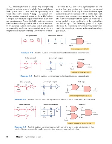
PLC contact symbolism is a simple way of expressing
                                                                        Because the PLC uses ladder logic diagrams, the con-
               the control logic in terms of symbols. These symbols are   version from any existing relay logic to programmed
               basically the same as those used for representing hard-  logic is simplified. Each rung is a combination of input
               wired relay control circuits. A rung is the contact sym-  conditions (symbols) connected from left to right, with
               bolism required to control an output. Some PLCs allow   the symbol that represents the  output at the far right.
               a rung to have multiple outputs while others allow only   The symbols that represent the inputs are connected in
               one output per rung. A complete ladder logic program then   series, parallel, or some combination of the two to obtain
               consists of several rungs, each of which controls an output.   the desired logic.  The following group of examples
               In programmed logic all mechanical switch contacts are   illustrates  the relationship between the relay ladder sche-
               represented by a software contact symbol and all electro-  matic, the ladder logic program, and the equivalent logic
               magnetic coils are represented by a software coil symbol.  gate circuit.


                                     Relay schematic         Ladder logic program
                                                                                            Gate logic
                                   LS1    LS2    SOL         A      B      Y         A
                                                                                                        Y
                                                            LS1    LS2    SOL        B                 Output
                                                                                   Inputs
                                                                                      Boolean equation: AB = Y
                                Example 4-1  Two limit switches connected in series and used to control a solenoid valve.


                                    Relay schematic           Ladder logic program
                                                                                             Gate logic
                                   LS1        SOL              A          Y
                                                                                      A
                                                                                                         Y
                                                               LS1       SOL
                                   LS2                                                B
                                                               B                                        Output
                                                                                     Inputs
                                                              LS2
                                                                                       Boolean equation: A + B = Y
                               Example 4-2  Two limit switches connected in parallel and used to control a solenoid valve.


                              Relay schematic          Ladder logic program                   Gate logic
                                          PL
                           LS1      PS                  A       C     Y          A
                                          G                                                    A   B
                                                       LS1     PS    PL                                         Y
                           LS2                                                   B
                                                        B                        C                            Output
                                                                                Inputs
                                                       LS2
                                                                                     Boolean equation: (A + B)C = Y
                        Example 4-3  Two limit switches connected in parallel with each other and in series with a pressure switch.

                              Relay schematic           Ladder logic program                  Gate logic
                                           PL                                   A
                           LS1     FS1                  A      C      Y                        A + B
                                           R
                                                        LS1    FS1    PL        B
                                                                                                                Y
                           LS2     FS2                  B      D                C                             Output
                                                       LS2     FS1              D              C + D
                                                                              Inputs
                                                                                  Boolean equation: (A + B) (C + D) = Y

                        Example 4-4  Two limit switches connected in parallel with each other and in series with two sets of flow
                        switches (that are connected in parallel with each other), and used to control a pilot light.


               68         Chapter 4  Fundamentals of Logic


          pet73842_ch04_061-073.indd   68                                                                               03/11/15   3:52 PM