
Page 90 - Programmable Logic Controllers, Fifth Edition - Mobile version
P. 90
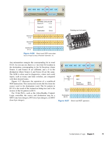
MOV  MVM  AND  OR  XOR  NOT  CLR

                                           Compare  Compute/Math  Move/Logical  File/Misc

                                                  XOR
                                                  BITWISE EXCLUS OR
                                                  Source A    Ι:1.0

                                                  Source B     Ι:3.0
                                                  Destination  O:4.0                  Rotating cam limit switch


                                      Source A  000000001010101 0
                                        Ι:1.0

                                      Source B  000000001110101 1
                                        Ι:3.0

                                    Destination  000000000100000 1
                                      O:4.0

                                   Figure 4-26  Word-level XOR instruction.
                                   Source: Image Courtesy of Rockwell Automation, Inc.


                   Any mismatches energize the corresponding bit in word
                   O:4.0. As you can see, there is a 1 in every bit location in    MOV  MVM  AND  OR  XOR  NOT  CLR
                   the destination corresponding to the bit locations where
                   Source  A and Source B are different, and a 0 in the            Compare  Compute/Math  Move/Logical  File/Misc
                   destination where Source A and Source B are the same.
                   The XOR is often used in diagnostics, where real-world
                   inputs, such as rotary cam limit switches, are compared        Input A    NOT
                   with their desired states.                                                NOT
                     Figure 4-27 illustrates the operation of a word-level
                   NOT instruction. This instruction inverts the bits from the               Source       B3:9
                                                                                             Destination
                                                                                                          B3:10
                   source word to the destination word. The bit pattern in
                   B3:10 is the result of the instruction being true and is the   Source
                   inverse of the bit pattern in B3:9.                           B3:9  0 00000001010101 0
                     For 32-bit PLCs, such as the Allen-Bradley Control-
                   Logix controller, the source and destination may be a     Destination  1 11111110101010 1
                   SINT (one-byte integer), INT (two-byte integer), or DINT    B3:10
                   (four-byte integer).                                  Figure 4-27  Word-level NOT operation.


                                                                                     Fundamentals of Logic  Chapter 4    71


          pet73842_ch04_061-073.indd   71                                                                               03/11/15   3:52 PM