
Page 257 - Icon Ridge Presents ORION
P. 257
Turning tools \ Technical introduction – turning - ISO turning
M M
16 RM1 16
a ( mm ) p 6,3 RM1 a ( mm ) p 6,3 10 RU RU
10
4 4
2,5 2,5
1,6 1,6
1 1
0,63 0,63
0,4 0,405 0,4 0,35 0,3
0,25 0,127 0,25 19°
0,16 0,16
15° 21°
0,1 0,1
0,025 0,04 0,063 0,1 0,16 0,25 0,4 0,63 1 1,6 2,5 0,025 0,04 0,063 0,1 0,16 0,25 0,4 0,63 1 1,6 2,5
f ( mm ) f ( mm )
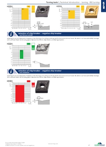
selection of chip breaker – negative chip breaker
non-ferrous metals
selecting the correct chip breaker depends on the infeed (ap), the cutting conditions and the feed values to be achieved. the aim is to achieve optimal chip breakage
with a defi ned infeed. the following graphs illustrate the different chip breakers and their applications.
N
16
a ( mm ) p 6,3 MN2
10
4 MN2
2,5
1,6
1
0,63
0,4
0,25
16°
0,16
0,1
0,025 0,04 0,063 0,1 0,16 0,25 0,4 0,63 1 1,6 2,5
f ( mm )
selection of chip breaker – negative chip breaker
cast materials
selecting the correct chip breaker depends on the infeed (ap), the cutting conditions and the feed values to be achieved. the aim is to achieve optimal chip breakage
with a defi ned infeed. the following graphs illustrate the different chip breakers and their applications.
K
16
a ( mm ) p 6,3 MK3 MK
10
4
2,5
1,6
1
0,63
0,4 0,25
0,25 0,08
0,16
15°
0,1
0,025 0,04 0,063 0,1 0,16 0,25 0,4 0,63 1 1,6 2,5
f ( mm )
Source: Hahn+Kolb Werkzeuge GmbH
Technical data subject to change. www.iconridge.com
Availability subject to country specific rules and regulations. 257
0516_EN_2018_KERN[21847773]-m.indd 519 12/17/2018 3:33:17 PM