
Page 262 - Icon Ridge Presents ORION
P. 262
Turning tools \ Technical introduction – turning - ISO turning
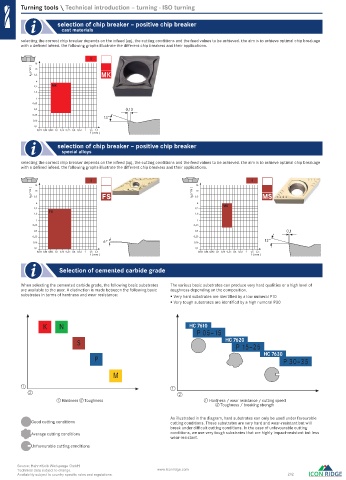
selection of chip breaker – positive chip breaker
cast materials
selecting the correct chip breaker depends on the infeed (ap), the cutting conditions and the feed values to be achieved. the aim is to achieve optimal chip breakage
with a defined infeed. the following graphs illustrate the different chip breakers and their applications.
K
16
a ( mm ) p 6,3 10 MK
4
2,5 MK
1,6
1
0,63
0,4 0,13
0,25
13°
0,16
0,1
0,025 0,04 0,063 0,1 0,16 0,25 0,4 0,63 1 1,6 2,5
f ( mm )
selection of chip breaker – positive chip breaker
special alloys
selecting the correct chip breaker depends on the infeed (ap), the cutting conditions and the feed values to be achieved. the aim is to achieve optimal chip breakage
with a defined infeed. the following graphs illustrate the different chip breakers and their applications.
S S
16 16
a ( mm ) p 6,3 10 FS a ( mm ) p 6,3 10 MS
4 4
MS
2,5 2,5
FS
1,6 1,6
1 1
0,63 0,63
0,4 0,4 0,1
0,25 0,25
0,16 6° 0,16 12°
0,1 0,1
0,025 0,04 0,063 0,1 0,16 0,25 0,4 0,63 1 1,6 2,5 0,025 0,04 0,063 0,1 0,16 0,25 0,4 0,63 1 1,6 2,5
f ( mm ) f ( mm )
Selection of cemented carbide grade
When selecting the cemented carbide grade, the following basic substrates The various basic substrates can produce very hard qualities or a high level of
are available to the user. A distinction is made between the following basic toughness depending on the composition.
substrates in terms of hardness and wear resistance: Very hard substrates are identified by a low numeral P10
Very tough substrates are identified by a high numeral P30
K N HC 7610
P 05–15
S HC 7620
P 15–25
HC 7630
P P 30–35
M
1 1
2
2
① Hardness ② Toughness ① Hardness / wear resistance / cutting speed
② Toughness / breaking strength
As illustrated in the diagram, hard substrates can only be used under favourable
Good cutting conditions cutting conditions. These substrates are very hard and wear-resistant but will
break under difficult cutting conditions. In the case of unfavourable cutting
Average cutting conditions conditions, we use very tough substrates that are highly impact-resistant but less
wear-resistant.
Unfavourable cutting conditions
Source: Hahn+Kolb Werkzeuge GmbH
Technical data subject to change. www.iconridge.com
Availability subject to country specific rules and regulations. 262
0524_EN_2018_KERN[21847785]-k.indd 524 12/17/2018 3:32:46 PM