Page 263 - Icon Ridge Presents ORION
P. 263

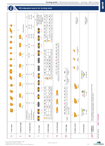
Turning tools \ Technical introduction – turning - ISO turning

                     ISO indexable inserts for turning tools


                                 80–250  130–380  130
                               U                  12  12.7  32  32
                                        X  Scalene insert shape or  dimensions of the   symbols 5, 6 or 7  deviating from the   standard  12  10  12  10  25  25  25.4  25  Symbols only  if required  Symbol N only  if required

                           Miscellaneous  N  50–150  80–200  25  09  08  9.52  8  20  19  20  19.05


                     O                            06  6  16  16


                               M  50–150  80–200  50–130  05  R  5  15  R  15.88
                                                     Incircle d  Incircle d


                                 50–150                        07  7.94
                               K    13  25                     09  9.52

                                                  33      15.88 19.05  06  6.35       double-chamfered and   rounded

                               J  50–150  5  25   27  22  08  12.7  05  04  5.56  4.76

                                                  16  16  06  9.52  T3  3.97          double-  chamfered
                                                  13  13  05  7.94  03  3.18
                               H  13  13  25
                                                  11  11  04  6.35  02  2.38
                                                  09    03  5.56  T1  1.98            chamfered and   rounded

                               G  25  25  50–130  08  T  V  W  4.76  01  1.59  MO  Round plate  (metr.)  N = neutral
                                                          Incircle d  Thickness s  00  Round plate  (inch)


                               E  25  25  25
                                                  25    25  25.4        32  3.2        chamfered
                                                  19    19              24  2.4
                               C  25  13  25      16    15  15.88 19.05  20  2.0                L = left

                                                  12  15  12  12.7      16  1.6
                                                  09  11  09  9.52      12  1.2        rounded
                               A  25  5  25       08      7.94          08  0.8                      These indications do not form part of the standard and are facultative.
                                                  06  05  07  06  6.35  5.56  04  02  0.4  0.2         e. g. -AS3 for chip shaper geometry "medium stress"

                               ± tolerances (m)  for incircle d  for test dimension m  for thickness s  04  C  D  S  4.76  Incircle d  00  Radius r  0  Corner radius  sharp  R = right  DCMT 11 T3 08-MP


              1.Insert shape  2.Clearance angle  3.Tolerance class  4.Insert type  5.Cutter length  6.Insert thickness  7.Cutter angle  8.Cutter version  9.Cut direction  10.Additional   indications


              D         C         M         T         11        T3        08                          -MP    Example: turning


       Source: Hahn+Kolb Werkzeuge GmbH
       Technical data subject to change.             www.iconridge.com
       Availability subject to country specific rules and regulations.                          263

   0524_EN_2018_KERN[21847785]-k.indd  525                                                            12/17/2018  3:32:47 PM
   258   259   260   261   262   263   264   265   266   267   268