
Page 156 - From GMS to LTE
P. 156
142 From GSM to LTE-Advanced Pro and 5G
layers except for the physical layer, which is handled in the Node‐B. The only exception
to this rule is the BCCH, which is under the control of the Node‐B. This is due to the
fact that the BCCH only broadcasts static information that does not have to be
repeatedly sent from the RNC to the Node‐B.
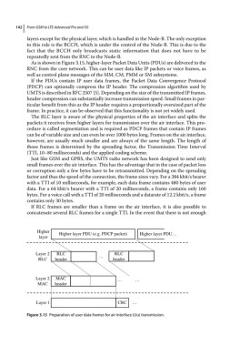
As is shown in Figure 3.15, higher‐layer Packet Data Units (PDUs) are delivered to the
RNC from the core network. This can be user data like IP packets or voice frames, as
well as control plane messages of the MM, CM, PMM or SM subsystems.
If the PDUs contain IP user data frames, the Packet Data Convergence Protocol
(PDCP) can optionally compress the IP header. The compression algorithm used by
UMTS is described in RFC 2507 [5]. Depending on the size of the transmitted IP frames,
header compression can substantially increase transmission speed. Small frames in par-
ticular benefit from this as the IP header requires a proportionally oversized part of the
frame. In practice, it can be observed that this functionality is not yet widely used.
The RLC layer is aware of the physical properties of the air interface and splits the
packets it receives from higher layers for transmission over the air interface. This pro-
cedure is called segmentation and is required as PDCP frames that contain IP frames
can be of variable size and can even be over 1000 bytes long. Frames on the air interface,
however, are usually much smaller and are always of the same length. The length of
those frames is determined by the spreading factor, the Transmission Time Interval
(TTI, 10–80 milliseconds) and the applied coding scheme.
Just like GSM and GPRS, the UMTS radio network has been designed to send only
small frames over the air interface. This has the advantage that in the case of packet loss
or corruption only a few bytes have to be retransmitted. Depending on the spreading
factor and thus the speed of the connection, the frame sizes vary. For a 384 kbit/s bearer
with a TTI of 10 milliseconds, for example, each data frame contains 480 bytes of user
data. For a 64 kbit/s bearer with a TTI of 20 milliseconds, a frame contains only 160
bytes. For a voice call with a TTI of 20 milliseconds and a datarate of 12.2 kbit/s, a frame
contains only 30 bytes.
If RLC frames are smaller than a frame on the air interface, it is also possible to
concatenate several RLC frames for a single TTI. In the event that there is not enough
Higher Higher layer PDU (e.g. PDCP packet) Higher layer PDU…
layer
Layer 2 RLC … RLC
RLC header header
Layer 2 MAC … …
MAC header
Layer 1 CRC …
Figure 3.15 Preparation of user data frames for air interface (Uu) transmission.