
Page 159 - From GMS to LTE
P. 159
Universal Mobile Telecommunications System (UMTS) and High-Speed Packet Access (HSPA) 145
DPDCH
DPCCH (User data and
(Physical layer higher layer signaling
signaling)
e.g., MM, CC, GMM/SM)
Multiplexer
Q-path I-path
3.84 MChips/s 3.84 MChips/s
spreading factor = x spreading factor = x
Modulator
Transfer of the data over the air interface
X = Spreading factor determined by
the user data rate.
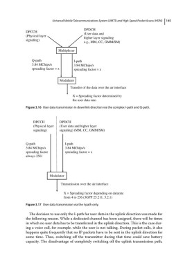
Figure 3.16 User data transmission in downlink direction via the complex I‐path and Q‐path.
DPCCH DPDCH
(Physical layer (User data and higher layer
signaling) signaling) (MM, CC, GMM/SM)
Q-path I-path
3.84 MChips/s 3.84 MChips/s
spreading factor spreading factor = x
always 256!
Modulator
Transmission over the air interface
X = Spreading factor depending on datarate
from 4 to 256 (3GPP 25.211, 5.2.1)
Figure 3.17 User data transmission via the I‐path only.
The decision to use only the I‐path for user data in the uplink direction was made for
the following reason. While a dedicated channel has been assigned, there will be times
in which no user data has to be transferred in the uplink direction. This is the case dur-
ing a voice call, for example, while the user is not talking. During packet calls, it also
happens quite frequently that no IP packets have to be sent in the uplink direction for
some time. Thus, switching off the transmitter during that time could save battery
capacity. The disadvantage of completely switching off the uplink transmission path,