
Page 444 - From GMS to LTE
P. 444
430 From GSM to LTE-Advanced Pro and 5G
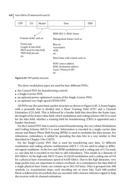
STF CE Header Data TRN
IEEE 802.11 MAC frame:
Contains fields such as: Management frames such as:
Frame type Beacon
Length of data field Association
MCS used for data field ACK
TRN field present etc.
etc.
Data frame with content such as:
MAC source address
MAC destination address
Layer 3 Protocol (IP)
etc.
Figure 6.20 PHY packet structure.
The three modulation types are used for four different PHYs:
the Control PHY for beamforming control;
●
a Single‐Carrier PHY;
●
an optional power‐optimized version of the Single‐Carrier PHY;
●
an optional very‐high‐speed OFDM PHY.
●
All PHYs use the same basic packet structure as shown in Figure 6.20. A frame begins
with a preamble that is divided into a Short Training Field (STF) and a Channel
Estimation (CE) field. This is followed by a header field that describes the frame type,
the length of the frame’s data field, which modulation and coding scheme (MCS) is used
for the data field, whether a training field for beamforming (TRN) is appended and a
header checksum.
For the Control PHY that is used to control beamforming, the very robust Modulation
and Coding Scheme (MCS) 0 is used. Information is encoded in a single‐carrier data
stream and Binary Phase Shift Keying (BPSK) is used to modulate the data stream. For
robustness, redundancy is added by spreading the data bits in a way similar to that
described in Chapter 3 for UMTS.
For the Single‐Carrier PHY that is used for transferring user data, 12 different
modulation and coding scheme combinations (MCS 1–12) are used to adapt to differ-
ent signal conditions. At the low end, BPSK modulation and a coding rate of 1/2 is used,
i.e. one data bit is encoded in two bits to add redundancy. This results in a datarate of
835 Mbit/s. At the high end, MCS 12 uses 16‐QAM modulation and a coding rate of 3/4
for a physical layer transmission speed of 4.620 Gbit/s. Due to the high datarates, very
large packet sizes are important to reduce overhead. As a consequence the data field of
a single physical layer frame can contain up to 262.143 bytes. Data is grouped into 448
symbols, i.e. transmission steps, each encoding one or more bits. Each 448‐symbol
block is followed by 64 symbols that are encoded with a known reference signal to help
the receiver with its channel estimation.