


Page 1028 - Basic Electrical Engineering
P. 1028
This is the peak of the reverse voltage or peak-inverse voltage (PIV) which is
               getting applied to the diode in every alternate half cycles.
                  It is seen that a diode works as a closed switch during the positive half

               cycle of the input voltage and works as an open switch during the negative
               half cycle. The output voltage appears across the load during the positive half

               cycle only. The load voltage and load current although positive all the time
               (i.e., unidirectional) are fluctuating dc as its magnitudes changing. Our aim

               will be to obtain steady dc at the output.
                  The average value of this fluctuating dc as also its RMS values can be


               calculated as                    respectively.


                  The performance parameters of a half-wave rectifier output are calculated
               in terms of the output dc current (i.e., the average value of the rectified

               wave), the RMS value of the output current, the output voltage, ripple factor,
               peak inverse voltage, etc.


                                       15.1.3 Analysis of Half-wave Rectifier


               The equation for a sinusoidal voltage is written as ν = V  sin θ and for a
                                                                                   m
               sinusoidal current,

                                                       i = I  sin θ,
                                                            m


               where i is the instantaneous value, I  is the maximum value, and θ = ωt.
                                                          m


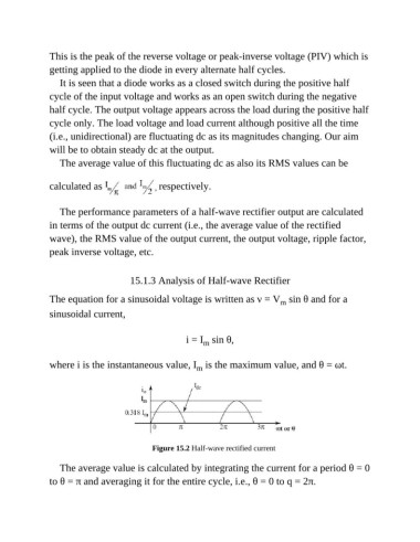
                                             Figure 15.2 Half-wave rectified current


                  The average value is calculated by integrating the current for a period θ = 0
               to θ = π and averaging it for the entire cycle, i.e., θ = 0 to q = 2π.

