
Page 133 - Basic Electrical Engineering
P. 133
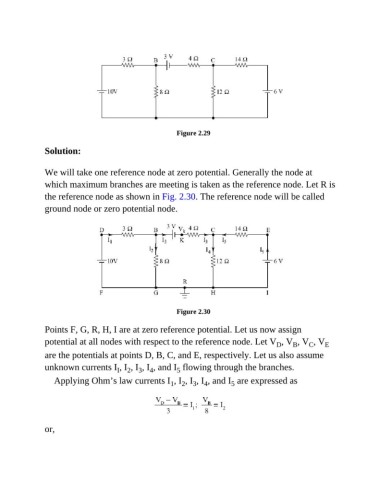
Figure 2.29


               Solution:


               We will take one reference node at zero potential. Generally the node at
               which maximum branches are meeting is taken as the reference node. Let R is

               the reference node as shown in Fig. 2.30. The reference node will be called
               ground node or zero potential node.


                                                          Figure 2.30


               Points F, G, R, H, I are at zero reference potential. Let us now assign
               potential at all nodes with respect to the reference node. Let V , V , V , V               E
                                                                                          D
                                                                                               B
                                                                                                    C
               are the potentials at points D, B, C, and E, respectively. Let us also assume
               unknown currents I , I , I , I , and I  flowing through the branches.
                                                          5
                                          2
                                       I
                                              3
                                                 4
                  Applying Ohm’s law currents I , I , I , I , and I  are expressed as
                                                                           5
                                                                   4
                                                        1
                                                            2
                                                               3
               or,