Page 268 - Basic Electrical Engineering
P. 268

c.  2.5 Ω
                         d.  5 Ω.

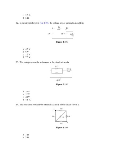
                 32.  In the circuit shown in Fig. 2.191, the voltage across terminals A and B is


                                                           Figure 2.191


                         a.  4.5 V
                         b.  6 V
                         c.  1.5 V
                         d.  7.5 V.


                 33.  The voltage across the resistances in the circuit shown is


                                                           Figure 2.192


                         a.  24 V
                         b.  12 V
                         c.  48 V
                         d.  4.8 V.

                 34.  The resistance between the terminals A and B of the circuit shown is


                                                           Figure 2.193


                         a.  1 Ω
                         b.  2 Ω
   263   264   265   266   267   268   269   270   271   272   273