
Page 269 - Basic Electrical Engineering
P. 269
c. 5 Ω
d. 1.5 Ω.
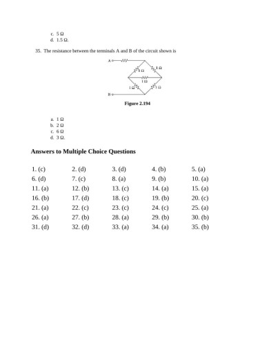
35. The resistance between the terminals A and B of the circuit shown is
Figure 2.194
a. 1 Ω
b. 2 Ω
c. 6 Ω
d. 3 Ω.
Answers to Multiple Choice Questions
1. (c) 2. (d) 3. (d) 4. (b) 5. (a)
6. (d) 7. (c) 8. (a) 9. (b) 10. (a)
11. (a) 12. (b) 13. (c) 14. (a) 15. (a)
16. (b) 17. (d) 18. (c) 19. (b) 20. (c)
21. (a) 22. (c) 23. (c) 24. (c) 25. (a)
26. (a) 27. (b) 28. (a) 29. (b) 30. (b)
31. (d) 32. (d) 33. (a) 34. (a) 35. (b)