
Page 289 - Basic Electrical Engineering
P. 289
angles with respect to the reference axis, there exists a space phase difference
between these three coils AA′, BB′, and CC′,. When EMFs will be induced in
these coils due to the cutting of the magnetic flux or due to change in flux
linkages, the EMFs will have similar time phase difference between them as
shown in Fig. 3.7.
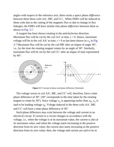
A magnet has been shown rotating in the anticlockwise direction.
Maximum flux will be cut by the coil AA′ at time, t = 0. Hence, maximum
voltage will be in the coil AA′ at time, t = 0 as has been shown as v in Fig.
A
3.7 Maximum flux will be cut by the coil BB′ after an elapse of angle 30°,
i.e., by the time the rotating magnet rotates by an angle of 30°. Similarly,
maximum flux will be cut by the coil CC′ after an elapse of time represented
by 60°.
Figure 3.7 Concept of phase and phase difference illustrated
The voltage waves in coil AA′, BB′, and CC′ will, therefore, have a time
phase difference of 30°. (30° corresponds to the time taken by the rotating
magnet to rotate by 30°). Since voltage v is appearing earlier than v , v is
A
B
A
said to be leading voltage v . Voltage induced in the three coils AA′, BB′,
B
and CC′ will have a time phase difference of 30°.
Such phase difference may exist between the voltage and current in an
electrical circuit. If current in a circuit changes in accordance with the
voltage, i.e., when the voltage is at its maximum value, the current is also at
its maximum value, and when the voltage starts increasing in the positive
direction from its zero value, the current also starts increasing in the positive
direction from its zero value; then, the voltage and current are said to be in