
Page 301 - Basic Electrical Engineering
P. 301
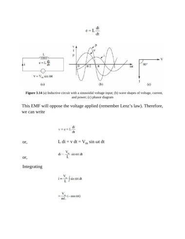
Figure 3.14 (a) Inductive circuit with a sinusoidal voltage input; (b) wave shapes of voltage, current,
                                                and power; (c) phasor diagram

               This EMF will oppose the voltage applied (remember Lenz’s law). Therefore,

               we can write


                or,                    L di = v dt = V  sin ωt dt
                                                         m


                or,


                Integrating