
Page 304 - Basic Electrical Engineering
P. 304
or,
or, V = I X L
If V is taken as the reference axis, we can represent V as a phasor and
represent as V ∠ 0°
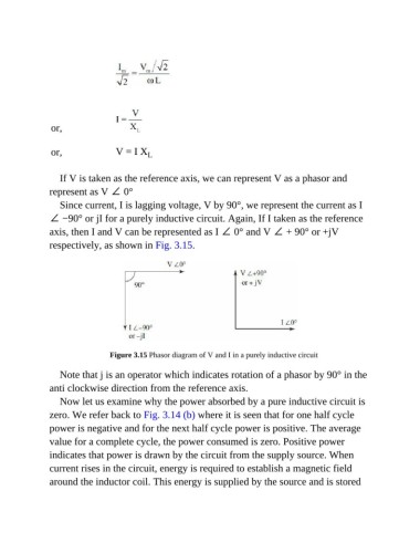
Since current, I is lagging voltage, V by 90°, we represent the current as I
∠ −90° or jI for a purely inductive circuit. Again, If I taken as the reference
axis, then I and V can be represented as I ∠ 0° and V ∠ + 90° or +jV
respectively, as shown in Fig. 3.15.
Figure 3.15 Phasor diagram of V and I in a purely inductive circuit
Note that j is an operator which indicates rotation of a phasor by 90° in the
anti clockwise direction from the reference axis.
Now let us examine why the power absorbed by a pure inductive circuit is
zero. We refer back to Fig. 3.14 (b) where it is seen that for one half cycle
power is negative and for the next half cycle power is positive. The average
value for a complete cycle, the power consumed is zero. Positive power
indicates that power is drawn by the circuit from the supply source. When
current rises in the circuit, energy is required to establish a magnetic field
around the inductor coil. This energy is supplied by the source and is stored