
Page 378 - Basic Electrical Engineering
P. 378
Note that voltage across the parallel branches is also equal to I Z or I Z .
B B
A A
The complete phasor diagram is shown in Fig. 3.63.
Figure 3.63 Phasor diagram representing voltages and currents in the circuit of Fig. 3.55
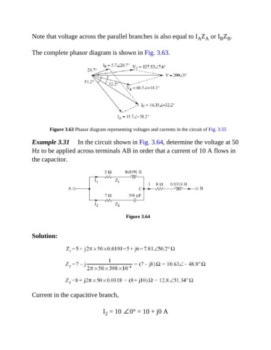
Example 3.31 In the circuit shown in Fig. 3.64, determine the voltage at 50
Hz to be applied across terminals AB in order that a current of 10 A flows in
the capacitor.
Figure 3.64
Solution:
Current in the capacitive branch,
I = 10 ∠0° = 10 + j0 A
2