
Page 387 - Basic Electrical Engineering
P. 387
them and the circuit as a whole appears to be a resistive only. The variation of
circuit current as the frequency changes at different values of circuit
resistance have been shown in Fig. 3.68 (a).
As can be noticed from the Fig. 3.68, at lower values of R, i.e., when R =
R the sharpness of the current curve is increased. At the resonant frequency
1
when current is at its maximum, the reactive power which oscillates between
the inductor and the capacitor is much higher than the resistive power.
Quality factor
The ratio of the reactive power to the resistive power is called the quality
factor. Quality factor is also defined as the ratio of voltage drop appearing
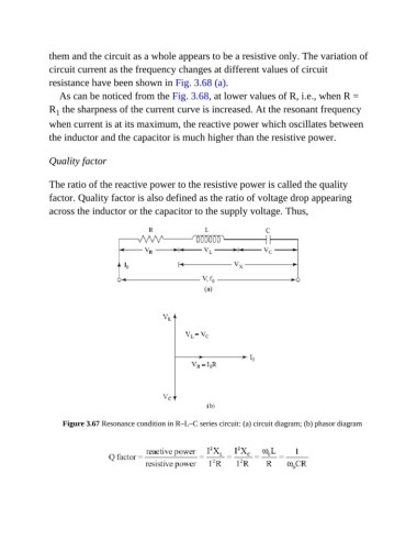
across the inductor or the capacitor to the supply voltage. Thus,
Figure 3.67 Resonance condition in R–L–C series circuit: (a) circuit diagram; (b) phasor diagram