
Page 385 - Basic Electrical Engineering
P. 385
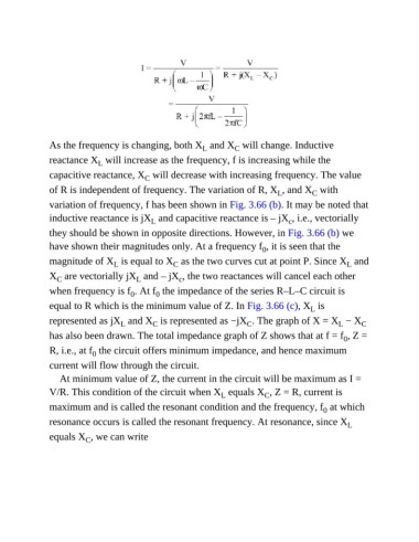
As the frequency is changing, both X  and X  will change. Inductive
                                                            L
                                                                     C
               reactance X  will increase as the frequency, f is increasing while the
                              L
               capacitive reactance, X  will decrease with increasing frequency. The value
                                           C
               of R is independent of frequency. The variation of R, X , and X  with
                                                                                            C
                                                                                  L
               variation of frequency, f has been shown in Fig. 3.66 (b). It may be noted that
               inductive reactance is jX  and capacitive reactance is – jX , i.e., vectorially
                                                                                     c
                                             L
               they should be shown in opposite directions. However, in Fig. 3.66 (b) we
               have shown their magnitudes only. At a frequency f , it is seen that the
                                                                              0
               magnitude of X  is equal to X  as the two curves cut at point P. Since X  and
                                                    C
                                                                                                      L
                                  L
               X  are vectorially jX  and – jX , the two reactances will cancel each other
                                         L
                                                     c
                  C
               when frequency is f . At f  the impedance of the series R–L–C circuit is
                                       0
                                               0
               equal to R which is the minimum value of Z. In Fig. 3.66 (c), X  is
                                                                                            L
               represented as jX  and X  is represented as −jX . The graph of X = X  − X                   C
                                                                                                    L
                                                                         C
                                    L
                                              C
               has also been drawn. The total impedance graph of Z shows that at f = f , Z =
                                                                                                     0
               R, i.e., at f  the circuit offers minimum impedance, and hence maximum
                            0
               current will flow through the circuit.
                  At minimum value of Z, the current in the circuit will be maximum as I =
               V/R. This condition of the circuit when X  equals X , Z = R, current is
                                                                              C
                                                                  L
               maximum and is called the resonant condition and the frequency, f  at which
                                                                                               0
               resonance occurs is called the resonant frequency. At resonance, since X                L

               equals X , we can write
                          C