Page 401 - Basic Electrical Engineering
P. 401

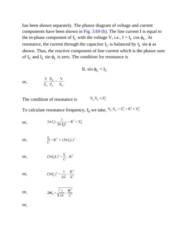
has been shown separately. The phasor diagram of voltage and current
               components have been shown in Fig. 3.69 (b). The line current I is equal to
               the in-phase component of I  with the voltage V, i.e., I = I  cos ϕ . At
                                                                                              L
                                                                                     L
                                                 L
               resonance, the current through the capacitor I  is balanced by I  sin ϕ as
                                                                      C
                                                                                           L
               shown. Thus, the reactive component of line current which is the phasor sum
               of I  and I  sin ϕ  is zero. The condition for resonance is
                    C
                                    L
                            L

                                                      IL sin ϕ  = I  C
                                                               L


               or,


               The condition of resonance is


               To calculate resonance frequency, f  we take,
                                                          0


               or,


               or,


               or,


               or,


               or,


               or,
   396   397   398   399   400   401   402   403   404   405   406