
Page 617 - Basic Electrical Engineering
P. 617
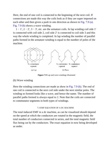
Here, the end of one coil is connected to the beginning of the next coil. If
               connections are made this way the coils look as if they are super imposed on
               each other and then given a push in one direction as shown in Fig. 7.9 (a).

               Fig. 7.9 (b) shows a wave winding.
                  1 − 1′, 2 − 2′, 3 − 3′, etc. are the armature coils. In lap winding coil side 1′

               is connected with coil side 2, coil side 2′ is connected to coil side 3 and this
               way the whole winding is completed. In lap winding the number of parallel

               paths formed in the armature winding is equal to the number of poles of the
               machine.


                                           Figure 7.9 Lap and wave windings illustrated

               (b) Wave winding


               Here the winding connections are made as show in Fig. 7.9 (b). The end of
               one coil is connected to the next coil side under the next similar poles. The

               winding so formed looks like a wave, and hence the name. The number of
               parallel paths formed is always equal to 2. Note that the coils are connected
               to commutator segments in both types of windings.


                                          7.3 EMF EQUATION OF A DC MACHINE
               The total induced EMF in a dc machine, as can be visualized should depend

               on the speed at which the conductors are rotated in the magnetic field, the
               total number of conductors connected in series, and the total magnetic field

               flux being cut by the conductors. The exact equation in now being developed
               as under.