
Page 614 - Basic Electrical Engineering
P. 614
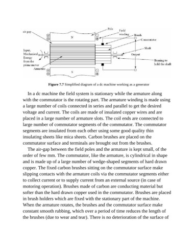
Figure 7.7 Simplified diagram of a dc machine working as a generator

                  In a dc machine the field system is stationary while the armature along

               with the commutator is the rotating part. The armature winding is made using
               a large number of coils connected in series and parallel to get the desired

               voltage and current. The coils are made of insulated copper wires and are
               placed in a large number of armature slots. The coil ends are connected to
               large number of commutator segments of the commutator. The commutator

               segments are insulated from each other using some good quality thin
               insulating sheets like mica sheets. Carbon brushes are placed on the

               commutator surface and terminals are brought out from the brushes.
                  The air-gap between the field poles and the armature is kept small, of the

               order of few mm. The commutator, like the armature, is cylindrical in shape
               and is made up of a large number of wedge-shaped segments of hard drawn

               copper. The fixed carbon brushes sitting on the commutator surface make
               slipping contacts with the armature coils via the commutator segments either
               to collect current or to supply current from an external source (in case of

               motoring operation). Brushes made of carbon are conducting material but
               softer than the hard drawn copper used in the commutator. Brushes are placed

               in brush holders which are fixed with the stationary part of the machine.
               When the armature rotates, the brushes and the commutator surface make
               constant smooth rubbing, which over a period of time reduces the length of

               the brushes (due to wear and tear). There is no deterioration of the surface of