
Page 610 - Basic Electrical Engineering
P. 610
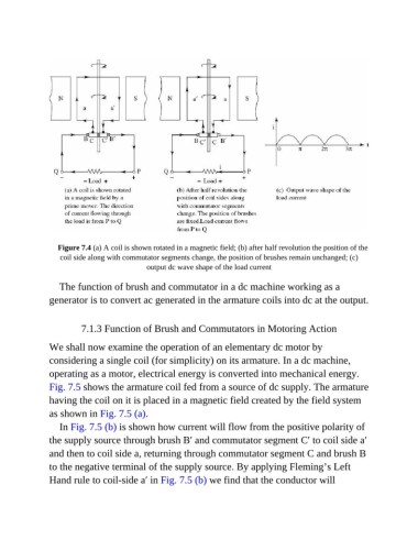
Figure 7.4 (a) A coil is shown rotated in a magnetic field; (b) after half revolution the position of the
                   coil side along with commutator segments change, the position of brushes remain unchanged; (c)
                                            output dc wave shape of the load current


                  The function of brush and commutator in a dc machine working as a
               generator is to convert ac generated in the armature coils into dc at the output.


                         7.1.3 Function of Brush and Commutators in Motoring Action

               We shall now examine the operation of an elementary dc motor by
               considering a single coil (for simplicity) on its armature. In a dc machine,

               operating as a motor, electrical energy is converted into mechanical energy.
               Fig. 7.5 shows the armature coil fed from a source of dc supply. The armature

               having the coil on it is placed in a magnetic field created by the field system
               as shown in Fig. 7.5 (a).

                  In Fig. 7.5 (b) is shown how current will flow from the positive polarity of
               the supply source through brush B′ and commutator segment C′ to coil side a′
               and then to coil side a, returning through commutator segment C and brush B

               to the negative terminal of the supply source. By applying Fleming’s Left
               Hand rule to coil-side a′ in Fig. 7.5 (b) we find that the conductor will