
Page 611 - Basic Electrical Engineering
P. 611
experience an upward force whereas the coil side a will experience a
downward force. These two forces would create a torque to rotate the
armature in the anticlockwise direction.
After every half revolution, i.e., for every rotation of 180° mechanical, coil
side a′ along with the connected commutator segment C′ will change
positions with the coil side a and the connected commutator segment C. After
half revolution it is seen that the direction of current in the coil has reversed.
Earlier as in Fig. 7.5 (b), current was flowing from a′ to a and after half
revolution current is flowing from a to a′ as shown in Fig. 7.5 (c).
Supply polarities remaining fixed, it is seen that current in the armature
coil is alternating its direction. However, the direction of the rotation of the
coil, as obtained, is unidirectional, i.e., in this case in the anti clockwise
direction. The students are advised to check the nature of torque developed in
the armature if the supply is given from a dc source but through the brush and
slip-ring arrangement. It will be seen that the torque developed will be
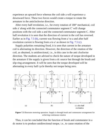
alternating in every half cycle thereby net torque being zero.
Figure 7.5 Illustrates motoring operation. Supply is through brush and commutator arrangement for
achieving continuous rotation
Thus, it can be concluded that the function of brush and commutator in a
dc motor is to produce unidirectional torque, i.e., to cause rotation of the