
Page 618 - Basic Electrical Engineering
P. 618
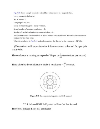
Fig. 7.10 shows a single conductor rotated by a prime mover in a magnetic field.

                  Let us assume the following:
                  No. of poles = P.

                  Flux per pole = ϕ Wb.
                  Speed of the driving prime mover = N rpm.

                  Actual number of armature conductors = Z.
                  Number of parallel paths of the armature winding = A.

                  Induced EMF in the conductors will be due to relative velocity between the conductor and the flux
                  produced by the field poles.

                  When the conductor in Fig. 7.10 makes 1 revolution, the flux cut by the conductor = Pϕ Wbs.


                  (The students will appreciate that if there were two poles and flux per pole
               was ϕ Wbs.


               The conductor is rotating at a speed of N rpm or   (revolutions per second)


               Time taken by the conductor to make 1 revolution =   seconds.


                                      Figure 7.10 Development of equation for EMF induced


                             7.3.1 Induced EMF Is Equated to Flux Cut Per Second


               Therefore, induced EMF in 1 conductor