
Page 626 - Basic Electrical Engineering
P. 626
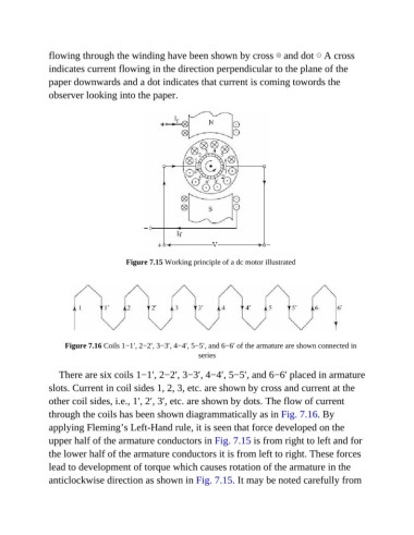
flowing through the winding have been shown by cross ⊗ and dot ⊙ A cross
               indicates current flowing in the direction perpendicular to the plane of the
               paper downwards and a dot indicates that current is coming towords the

               observer looking into the paper.


                                      Figure 7.15 Working principle of a dc motor illustrated


                    Figure 7.16 Coils 1−1′, 2−2′, 3−3′, 4−4′, 5−5′, and 6−6′ of the armature are shown connected in
                                                            series


                  There are six coils 1−1′, 2−2′, 3−3′, 4−4′, 5−5′, and 6−6′ placed in armature
               slots. Current in coil sides 1, 2, 3, etc. are shown by cross and current at the

               other coil sides, i.e., 1′, 2′, 3′, etc. are shown by dots. The flow of current
               through the coils has been shown diagrammatically as in Fig. 7.16. By
               applying Fleming’s Left-Hand rule, it is seen that force developed on the

               upper half of the armature conductors in Fig. 7.15 is from right to left and for
               the lower half of the armature conductors it is from left to right. These forces

               lead to development of torque which causes rotation of the armature in the
               anticlockwise direction as shown in Fig. 7.15. It may be noted carefully from