
Page 758 - Basic Electrical Engineering
P. 758
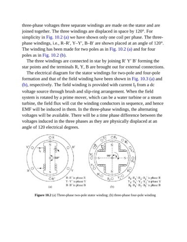
three-phase voltages three separate windings are made on the stator and are
               joined together. The three windings are displaced in space by 120°. For
               simplicity in Fig. 10.2 (a) we have shown only one coil per phase. The three-

               phase windings, i.e., R–R′, Y–Y′, B–B′ are shown placed at an angle of 120°.
               The winding has been made for two poles as in Fig. 10.2 (a) and for four

               poles as in Fig. 10.2 (b).
                  The three windings are connected in star by joining R′ Y′ B′ forming the

               star points and the terminals R, Y, B are brought out for external connections.
                  The electrical diagram for the stator windings for two-pole and four-pole

               formation and that of the field winding have been shown in Fig. 10.3 (a) and
               (b), respectively. The field winding is provided with current I  from a dc
                                                                                         f
               voltage source through brush and slip-ring arrangement. When the field
               system is rotated by a prime mover, which can be a water turbine or a steam

               turbine, the field flux will cut the winding conductors in sequence, and hence
               EMF will be induced in them. In the three-phase windings, the alternating
               voltages will be available. There will be a time phase difference between the

               voltages induced in the three phases as they are physically displaced at an
               angle of 120 electrical degrees.


                        Figure 10.2 (a) Three-phase two-pole stator winding; (b) three-phase four-pole winding