
Page 763 - Basic Electrical Engineering
P. 763
10.8 INDUCED EMF IN A SYNCHRONOUS MACHINE
In synchronous machines, the armature winding is made on the stator. The
rotor consists of magnetic poles excited by dc field current. The rotor poles
are rotated by a prime mover, may be a steam turbine or a water turbine, as
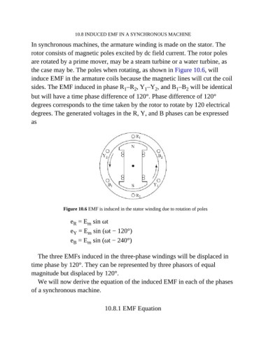
the case may be. The poles when rotating, as shown in Figure 10.6, will
induce EMF in the armature coils because the magnetic lines will cut the coil
sides. The EMF induced in phase R –R , Y –Y , and B –B will be identical
2
1
2
1
2
1
but will have a time phase difference of 120°. Phase difference of 120°
degrees corresponds to the time taken by the rotor to rotate by 120 electrical
degrees. The generated voltages in the R, Y, and B phases can be expressed
as
Figure 10.6 EMF is induced in the stator winding due to rotation of poles
e = E sin ωt
m
R
e = E sin (ωt − 120°)
m
Y
e = E sin (ωt − 240°)
B
m
The three EMFs induced in the three-phase windings will be displaced in
time phase by 120°. They can be represented by three phasors of equal
magnitude but displaced by 120°.
We will now derive the equation of the induced EMF in each of the phases
of a synchronous machine.
10.8.1 EMF Equation