
Page 780 - Basic Electrical Engineering
P. 780
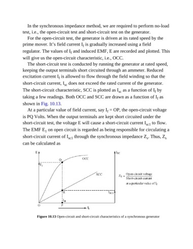
In the synchronous impedance method, we are required to perform no-load
               test, i.e., the open-circuit test and short-circuit test on the generator.
                  For the open-circuit test, the generator is driven at its rated speed by the

               prime mover. It’s field current I  is gradually increased using a field
                                                      f
               regulator. The values of I  and induced EMF, E are recorded and plotted. This
                                              f
               will give us the open-circuit characteristic, i.e., OCC.

                  The short-circuit test is conducted by running the generator at rated speed,
               keeping the output terminals short circuited through an ammeter. Reduced

               excitation current I  is allowed to flow through the field winding so that the
                                      f
               short-circuit current, I  does not exceed the rated current of the generator.
                                          sc
               The short-circuit characteristic, SCC is plotted as I  as a function of I  by
                                                                            sc
                                                                                                   f
               taking a few readings. Both OCC and SCC are drawn as a function of I  as
                                                                                                     f
               shown in Fig. 10.13.

                  At a particular value of field current, say I  = OP, the open-circuit voltage
                                                                     f
               is PQ Volts. When the output terminals are kept short circuited under the
               short-circuit test, the voltage E will cause a short-circuit current I  to flow.
                                                                                              sc1
               The EMF E  on open circuit is regarded as being responsible for circulating a
                              1
               short-circuit current of I  through the synchronous impedance Z . Thus, Z                  s
                                                                                              s
                                            sc1
               can be calculated as


                        Figure 10.13 Open-circuit and short-circuit characteristics of a synchronous generator