
Page 777 - Basic Electrical Engineering
P. 777
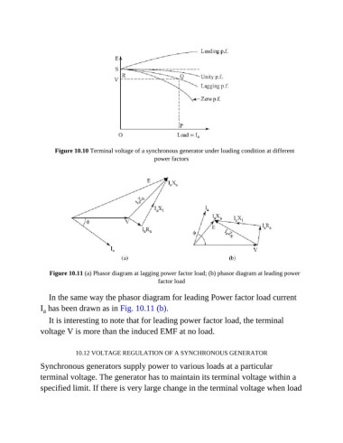
Figure 10.10 Terminal voltage of a synchronous generator under loading condition at different
                                                        power factors


                   Figure 10.11 (a) Phasor diagram at lagging power factor load; (b) phasor diagram at leading power
                                                         factor load


                  In the same way the phasor diagram for leading Power factor load current
               I  has been drawn as in Fig. 10.11 (b).
                a
                  It is interesting to note that for leading power factor load, the terminal
               voltage V is more than the induced EMF at no load.


                            10.12 VOLTAGE REGULATION OF A SYNCHRONOUS GENERATOR

               Synchronous generators supply power to various loads at a particular

               terminal voltage. The generator has to maintain its terminal voltage within a
               specified limit. If there is very large change in the terminal voltage when load