
Page 776 - Basic Electrical Engineering
P. 776
fictitious (not real) armature reactance which replaces the effect of armature
reaction. Again
E = V + I R + jI (X + X )
a
a
a a
l
= V + I R + jI X
a a
a s
= V + I (R + jX )
s
a
a
= V + I Z
a s
where X = X + X is called the synchronous reactance and Z = R + jX is
s
s
s
a
1
a
called the synchronous impedance.
The vector sum of R and X is called the synchronous impedance. The
S
a
effect of armature voltage drop due to armature resistance and synchronous
reactance, i.e., synchronous impedance at different power factor load, has
been shown in Fig.10.10. It is interesting to note that at leading power factor
load the terminal voltage of the synchronous generator increases with
increase in load.
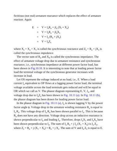
Let OS represent the voltage induced at no load, i.e., E. When a load
current I equivalent to OP flows at a lagging power factor load, the terminal
a
voltage available across the load terminals gets reduced and will be equal to
OR which we call as V. The phasor diagram representing E, V, I , and
a
voltage drop due to I Z has been shown in Fig. 10.11 (a). In Fig. 10.11 (b),
a s
the phasor diagram has been drawn for leading power factor load.
In the phasor diagram in Fig. 10.11 (a), I is shown lagging V by the power
a
factor angle ϕ. Voltage drop in the armature winding resistance R is equal to
a
I R . This voltage drop of I R has been shown parallel to I . This is because
a
a
a
a
a
R does not have any direction. Voltage drop across an inductive reactance is
a
shown perpendicular to I and leading I . Therefore, drops I X and I X have
a 1
a
a a
a
been shown perpendicular to I . The sum of I R + j I (X + X ) is I Z ,
1
a
a
a
s
a
a
a
where Z = R + j (X + X ) = R + j X . The sum of V and I Z is equal to E.
1
a
s
a
a
s
a
s