
Page 787 - Basic Electrical Engineering
P. 787
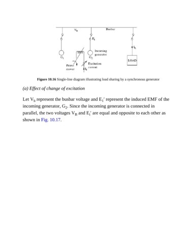
Figure 10.16 Single-line diagram illustrating load sharing by a synchronous generator

               (a) Effect of change of excitation


               Let V  represent the busbar voltage and E ′ represent the induced EMF of the
                      b
                                                                  1
               incoming generator, G . Since the incoming generator is connected in
                                          2
               parallel, the two voltages V  and E ′ are equal and opposite to each other as
                                                          i
                                                B
               shown in Fig. 10.17.