
Page 792 - Basic Electrical Engineering
P. 792
10.15.3 Effect of Change of Excitation of a Synchronous Motor
Let a synchronous motor carry a particular constant load and run at its
synchrons speed. The motor will draw a current I . The busbar voltage at the
a
motor terminals is V. The field windings in the rotor are excited by the field
current fed from a dc supply. When the rotor is rotating, the field flux will cut
the stator windings and induce EMF E on the stator windings. When the rotor
is rotating at synchronous speed, the magnitude of E will be proportional to
the field current. If the field current, I , is increased, E will increase; if I is
f
f
decreased, the magnitude of E will decrease. The angle of lag of E with
respect to the busbar voltage will depend on the mechanical load applied to
the motor shaft. We shall study the effect of change of excitation current I on
f
the magnitude of current drawn and the power factor of the motor.
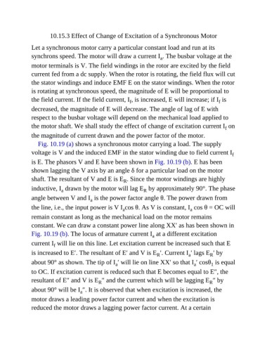
Fig. 10.19 (a) shows a synchronous motor carrying a load. The supply
voltage is V and the induced EMF in the stator winding due to field current I f
is E. The phasors V and E have been shown in Fig. 10.19 (b). E has been
shown lagging the V axis by an angle δ for a particular load on the motor
shaft. The resultant of V and E is E . Since the motor windings are highly
R
inductive, I drawn by the motor will lag E by approximately 90°. The phase
R
a
angle between V and I is the power factor angle θ. The power drawn from
a
the line, i.e., the input power is V I cos θ. As V is constant, I cos θ = OC will
a
a
remain constant as long as the mechanical load on the motor remains
constant. We can draw a constant power line along XX′ as has been shown in
Fig. 10.19 (b). The locus of armature current I at a different excitation
a
current I will lie on this line. Let excitation current be increased such that E
f
is increased to E′. The resultant of E′ and V is E ′. Current I ′ lags E ′ by
a
R
R
about 90° as shown. The tip of I ′ will lie on line XX′ so that I ′ cosθ is equal
a
a
1
to OC. If excitation current is reduced such that E becomes equal to E″, the
resultant of E″ and V is E ″ and the current which will be lagging E ″ by
R
R
about 90° will be I ″. It is observed that when excitation is increased, the
a
motor draws a leading power factor current and when the excitation is
reduced the motor draws a lagging power factor current. At a certain