


Page 885 - Basic Electrical Engineering
P. 885
The variation of magnetic coupling between two coils can be utilized to
               change M. Displacement of the core or a part of the core can cause change in
               M. The change in M will be measured by a bridge circuit and a proportional

               signal created for the measurement of displacement.


                                          12.7 POTENTIOMETRIC TRANSDUCER

               A potentiometric transducer is basically an electrical resistive transducer. A
               potentiometer is an electromechanical device having a resistance element

               with a sliding facility which enables changes in the resistance value at the
               output. The sliding contact is known as wiper, which may be translatory or
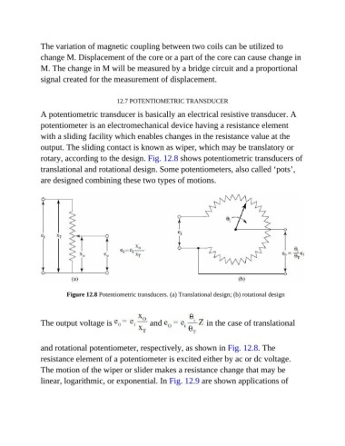
               rotary, according to the design. Fig. 12.8 shows potentiometric transducers of

               translational and rotational design. Some potentiometers, also called ‘pots’,
               are designed combining these two types of motions.


                         Figure 12.8 Potentiometric transducers. (a) Translational design; (b) rotational design


               The output voltage is                  and                 in the case of translational


               and rotational potentiometer, respectively, as shown in Fig. 12.8. The

               resistance element of a potentiometer is excited either by ac or dc voltage.
               The motion of the wiper or slider makes a resistance change that may be

               linear, logarithmic, or exponential. In Fig. 12.9 are shown applications of

