


Page 881 - Basic Electrical Engineering
P. 881
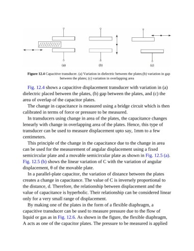
Figure 12.4 Capacitive transducer. (a) Variation in dielectric between the plates;(b) variation in gap
                                       between the plates; (c) variation in overlapping area


                  Fig. 12.4 shows a capacitive displacement transducer with variation in (a)
               dielectric placed between the plates, (b) gap between the plates, and (c) the

               area of overlap of the capacitor plates.
                  The change in capacitance is measured using a bridge circuit which is then

               calibrated in terms of force or pressure to be measured.
                  In transducers using change in area of the plates, the capacitance changes
               lenearly with change in overlapping area of the plates. Hence, this type of

               transducer can be used to measure displacement upto say, 1mm to a few
               centimeters.

                  This principle of the change in the capacitance due to the change in area
               can be used for the measurement of angular displacement using a fixed

               semicircular plate and a movable semicircular plate as shown in Fig. 12.5 (a).
               Fig. 12.5 (b) shows the linear variation of C with the variation of angular

               displacement, θ of the movable plate.
                  In a parallel-plate capacitor, the variation of distance between the plates
               creates a change in capacitance. The value of C is inversely proportional to

               the distance, d. Therefore, the relationship between displacement and the
               value of capacitance is hyperbolic. Their relationship can be considered linear

               only for a very small range of displacement.
                  By making one of the plates in the form of a flexible diaphragm, a
               capacitive transducer can be used to measure pressure due to the flow of

               liquid or gas as in Fig. 12.6. As shown in the figure, the flexible diaphragm,
               A acts as one of the capacitor plates. The pressure to be measured is applied

