


Page 980 - Basic Electrical Engineering
P. 980
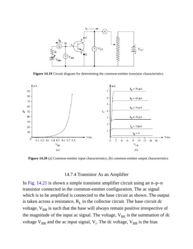
Figure 14.19 Circuit diagram for determining the common-emitter transistor characteristics


                   Figure 14.20 (a) Common-emitter input characteristics; (b) common-emitter output characteristics


                                          14.7.4 Transistor As an Amplifier

               In Fig. 14.21 is shown a simple transistor amplifier circuit using an n–p–n
               transistor connected in the common-emitter configuration. The ac signal

               which is to be amplified is connected to the base circuit as shown. The output
               is taken across a resistance, R  in the collector circuit. The base circuit dc
                                                   L
               voltage, V  is such that the base will always remain positive irrespective of
                            BB
               the magnitude of the input ac signal. The voltage, V  is the summation of dc
                                                                              BE
               voltage V  and the ac input signal, V . The dc voltage, V  is the bias
                                                                                     BB
                           BB
                                                              i

