


Page 983 - Basic Electrical Engineering
P. 983
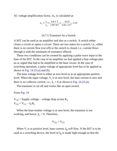
AC voltage amplification factor, A  is calculated as
                                                         V


                                            14.7.5 Transistor As a Switch


               A BJT can be used as an amplifier and also as a switch. A switch either
               closes a circuit or opens a circuit. There are two states for a switch, i.e., either

               there is no current flow (cut off) or the switch is closed, i.e., current flows
               through it with the minimum of resistance offered.

                  These two conditions can be created by applying a pulse wave input to the
               base of the BJT. In the case of an amplifier we had applied a bias voltage plus
               an ac signal that had to be amplified to the base circuit. In the case of

               switching operation, a pulse voltage of appropriate level has to be applied as
               shown in Fig. 14.23 (a) and (b).

                  The base voltage level is either at zero level or at an appropriate positive
               level. When the input voltage, V  is at zero level, the base current is zero and
                                                      i
               there is no collector current, i.e., I  = 0 as shown is Fig. 14.23 (a).
                                                        C
                  The transistor is cut off and works like an open switch.


               From Fig. 14


               V  = Supply voltage – voltage drop across R             2
                  CE
               V  = V     CC  – I R
                                 C 2
                  CE

                  When the base-emitter voltage is at zero level, the transistor is not
               working, and hence, I  = 0. Therefore,
                                         C

                                                        V  = V    CC
                                                          CE


                  When V  is at positive level, base current, I  will flow. If the BJT is to be
                                                                      B
                            i
               used as a switching device, the level of I  is made high enough so that the
                                                                B

