
Page 209 - Fiber Optic Communications Fund
P. 209
190 Fiber Optic Communications
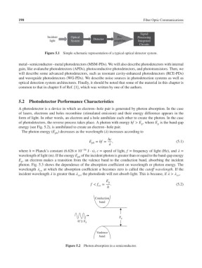
Signal
Incident Optical Pre- Processing
light System Detector amplifier Integrated
Circuits
Figure 5.1 Simple schematic representation of a typical optical detector system.
metal–semiconductor–metal photodetectors (MSM-PDs). We will also describe photodetectors with internal
gain, like avalanche photodetectors (APDs), photoconductive photodetectors, and phototransistors. Then, we
will describe some advanced photodetectors, such as resonant cavity-enhanced photodetectors (RCE-PDs)
and waveguide photodetectors (WG-PDs). We describe noise sources in photodetection systems as well as
optical detection system architectures. Finally, it should be noted that some of the material in this chapter is
common to that in chapter 8 of Ref. [1], which was written by one of the authors.
5.2 Photodetector Performance Characteristics
A photodetector is a device in which an electron–hole pair is generated by photon absorption. In the case
of lasers, electrons and holes recombine (stimulated emission) and their energy difference appears in the
form of light. In other words, an electron and a hole annihilate each other to create the photon. In the case
of photodetectors, the reverse process takes place. A photon with energy hf > E , where E is the band-gap
g g
energy (see Fig. 5.2), is annihilated to create an electron–hole pair.
The photon energy (E ) decreases as the wavelength () increases according to
ph
hc
E ph = hf = , (5.1)
where h = Planck’s constant (6.626 × 10 −34 J ⋅ s), c = speed of light, f = frequency of light (Hz), and =
wavelength of light (m). If the energy E of the incident photon is greater than or equal to the band-gap energy
ph
E , an electron makes a transition from the valence band to the conduction band, absorbing the incident
g
photon. Fig. 5.3 shows the dependence of the absorption coefficient on wavelength or photon energy. The
wavelength at which the absorption coefficient becomes zero is called the cutoff wavelength.Ifthe
co
incident wavelength is greater than , the photodiode will not absorb light. This is because, if > ,
co co
E g
f < f = . (5.2)
co
h
Conduction
band
E g
hf ≥ E g
Vanlence
band
Figure 5.2 Photon absorption in a semiconductor.