Page 270 - Fiber Optic Communications Fund
P. 270

Optical Amplifiers                                                                 251
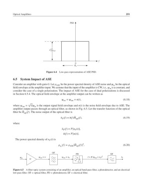

                                                     PSD


                                     ρ  LP
                                      ASE,sp


                                                                          f
                                                        0
                                                        B o

                                   Figure 6.4  Low-pass representation of ASE PSD.

           6.5  System Impact of ASE
           Consider an amplifier with gain G.Let  ASE  be the power spectral density of ASE noise and  be the optical
                                                                                    in
           field envelope at the amplifier input. We assume that the input of the amplifier is CW, i.e.,  is a constant, and
                                                                                  in
           consider the case of a single polarization. The impact of ASE for the case of dual polarizations is discussed
           in Section 6.5.4. The optical field envelope at the amplifier output can be written as
                                                 =   + n(t),                            (6.18)
                                                tot  out
                      √
           where   =  G is the output signal field envelope and n(t) is the noise field envelope due to ASE. The
                 out      in
           amplifier output passes through an optical filter, as shown in Fig. 6.5. Let the transfer function of the optical
                  ̃
           filter be H (f). The noise output of the optical filter is
                   opt
                                                        ̃
                                              ̃ n (f)= ̃n(f)H (f),                          (6.19)
                                               F         opt
           where
                                               ̃ n (f)= [n (t)],
                                                F       F
                                                ̃ n(f)= [n(t)].

            The power spectral density of n (t) is
                                     F
                                                              2
                                                        ̃
                                             (f)=  ASE |H (f)| ,                        (6.20)
                                                         opt
                                             n F
                                       OF
                                                         PD                        EF
                ψ             ψ out  + n       ψ out  + n F       I = R |ψ out  + n | 2   I F
                                                                           F
                 in
                       G
           Figure 6.5 A fiber-optic system consisting of an amplifier, an optical band-pass filter, a photodetector, and an electrical
           low-pass filter. OF = optical filter, PD = photodetector, EF = electrical filter.
   265   266   267   268   269   270   271   272   273   274   275