
Page 271 - Fiber Optic Communications Fund
P. 271
252 Fiber Optic Communications
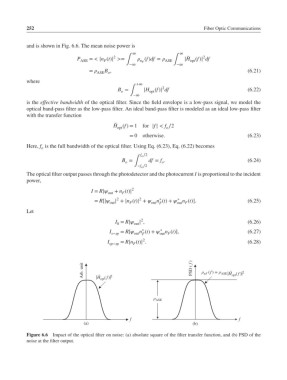
and is shown in Fig. 6.6. The mean noise power is
∞ ∞
2
̃
2
P ASE = < |n (t)| >= ∫ (f)df = ASE ∫ |H (f)| df
opt
F
n F
−∞ −∞
B ,
= ASE o (6.21)
where
+∞
2
B = |H (f)| df (6.22)
o ∫ opt
−∞
is the effective bandwidth of the optical filter. Since the field envelope is a low-pass signal, we model the
optical band-pass filter as the low-pass filter. An ideal band-pass filter is modeled as an ideal low-pass filter
with the transfer function
̃
H (f)= 1for |f| < f ∕2
o
opt
= 0 otherwise. (6.23)
Here, f is the full bandwidth of the optical filter. Using Eq. (6.23), Eq. (6.22) becomes
o
f o ∕2
B = df = f . (6.24)
o
o
∫
−f o ∕2
The optical filter output passes through the photodetector and the photocurrent I is proportional to the incident
power,
2
I = R|
F
out + n (t)|
2 2 ∗ ∗
= R[| | + |n (t)| + n (t)+ n (t)]. (6.25)
out F out F out F
Let
2
I = R| | , (6.26)
0
out
∗
∗
I s−sp = R[ n (t)+ n (t)], (6.27)
out F
out F
2
I sp−sp = R|n (t)| . (6.28)
F
Arb. unit H opt ( f) 2 PSD ( f ) ρ nF (f ) = ρ ASE H opt ( f ) 2
˜
˜
ρ ASE
f f
(a) (b)
Figure 6.6 Impact of the optical filter on noise: (a) absolute square of the filter transfer function, and (b) PSD of the
noise at the filter output.