Page 283 - Fiber Optic Communications Fund
P. 283

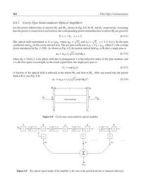
264                                                               Fiber Optic Communications


            6.6.1   Cavity-Type Semiconductor Optical Amplifiers
            Let the power reflectivities of mirrors M and M , shown in Fig. 6.8, be R and R , respectively. Assuming
                                                   2
                                             1
                                                                              2
                                                                        1
            that the power is conserved at each mirror, the corresponding power transmittivities at mirror M are given by
                                                                                        j
                                               T = 1 − R , j = 1, 2.                         (6.111)
                                                       j
                                                j
                                                          √             √
            The optical field transmitted at A is t  , where  =  P and |t | =  T , j = 1, 2. Let g be the gain
                                                             in
                                           1 in
                                                       in
                                                                    j
                                                                           j
            coefficient and  int  be the cavity internal loss. The net gain coefficient is g =Γg −  , where Γ is the overlap
                                                                               int
                                                                      s
            factor introduced in Eq. (3.109). As shown in Fig. 6.9, the partial optical field  at B after a single pass is
                                                                            0
                                                       √
                                              =  t t  G exp(i ),                       (6.112)
                                              0    in 1 2  s    0
            where  = 2nL∕ is the phase-shift due to propagation, n is the refractive index of the gain medium, and
                   0
             is the free-space wavelength. In the small-signal limit, the single-pass gain is
                                                 G = exp(g L).                               (6.113)
                                                   s       s
            A fraction of the optical field is reflected at the mirror M and then at M . After one round trip, the partial
                                                          2
                                                                       1
            field at B is (see Fig. 6.9)
                                                        √           3
                                           =  t r r t [ G exp(i )] ,                   (6.114)
                                           1    in 1 2 1 2  s     0
                                                       L
                                         M 1                         M 2
                                  ψ in   A                           B    ψ out
                                                   Gain medium
                                          R 1                      R 2
                                   Figure 6.8  Cavity-type semiconductor optical amplifier.


                    A              B               A                B                  B
                ψ in
                    t 1  G s e iφ 0  r 2  G s e iφ 0  r 1  G s e iφ 0  r 2  … ...  G s e iφ 0  r 2


                                   t 2                          t 2                 t 2
                                                                        … ...              … ...
                                    ψ 0                           ψ 1                 ψ n


                                                                ∑


                                                                ψ out
               Figure 6.9 The optical signal output of the amplifier is the sum of the partial fields due to repeated reflections.
   278   279   280   281   282   283   284   285   286   287   288